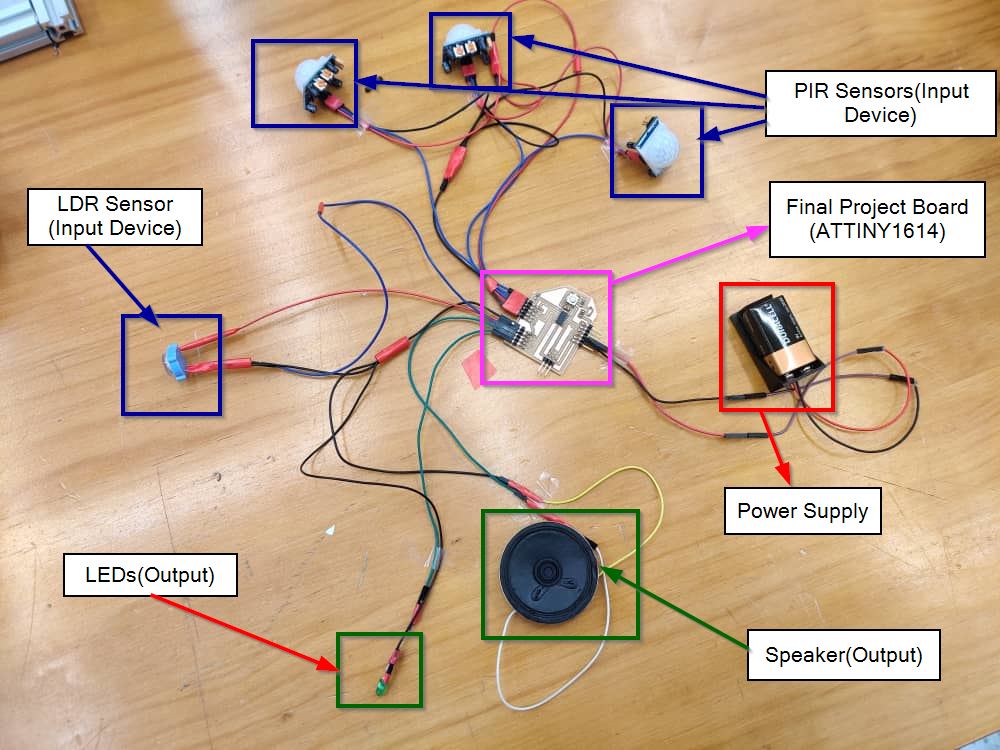
To clear confusions later on, I've created a specific color for output,input,VCC(Power) and GND connections. Red cable for VCC, Black for GND, Blue for Input devices and Green for Output devices.
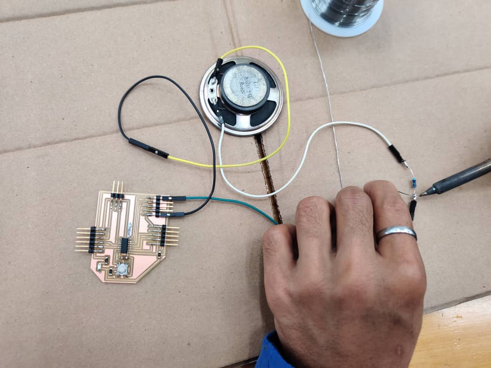
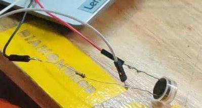
Here are some pictures of me soldering the components to connect the sensors. Rinchen was helping me along the way so Thank you Brother!!
I'll be using three PIR sensors and 1 LDR as Input Devices and 1 Speaker and String of LEDs as Output Devices. Didn't have the LEDs so right now I've just used a single green LED for showing the layout.
Codes Tried
During the Input Week, I used both the input devices, LDR and PIR sensor.
Using LDR to control LED
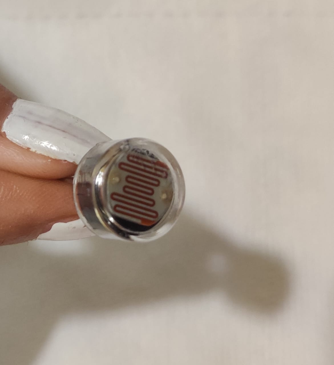
For my final project also, I've the same concept where by the LDR will sense the changes in the intensity of light shining on it and Control the LEDs.
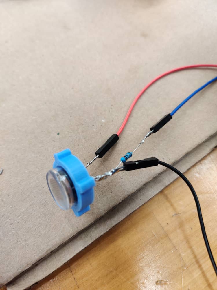
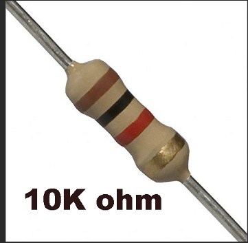
Soldered the PIR sensor to the resistor of 10K ohms and jumper wires so that it can directly connect with my board.
I used the output device board that I designed using ATTINY1614 as the microcontroller. I used 4 header pins so it was more than enough since PIR sensor needed only one signal pin.
Connected the Ground of my Board to one pin of the LDR sensor. The other end of the LDR sensor was soldered to 10K ohms resistor and the other end of the resistor connect to the VCC of my Board. For the signal pin, I soldered one jumper wire to the other end of the resistor which was connected to the end of LDR. Hence the circuit was completed
The LDR will detect the brightness in the room and when it's dark, the LED in my board will light up and vice versa.
Code I used is as follows and got the code from Here
       const int ledPin = 3;

       const int ldrPin = 2;

       void setup() {

       Serial.begin(9600);

       pinMode(ledPin, OUTPUT);

       pinMode(ldrPin, INPUT);

       }

       void loop() {

       int ldrStatus = analogRead(ldrPin);

       if (ldrStatus <=300) {

       digitalWrite(ledPin, HIGH);

       Serial.println("LDR is DARK, LED is ON");

       }

       else {

       digitalWrite(ledPin, LOW);

       Serial.println("---------------");

       }

       }
Here a video of how it worked.
Here is a video of how it worked with LED strips(connected to Relay and Battery)
Using PIR with LED
Actually I'm supposed to program the PIR with the Speaker for my final project but since I've used the PIR using the input week I didnt use any output devices and also I didn't have the speaker with me then. So instead as an output I used the LED on my board.
Connected the PIR GND and VCC to my Board GND and VCC and Connected the signal pin to my board Attiny1614 digital pin 2.
The LED on my board was connected to the Digital pin number 3 of ATTINY1614.
The LED was suppose to Light up when the PIR sensor senses movement.
Shown below is the code I used which I got it from here.Made the changes according to my board Pin.
  int LED = 3;
  int PIR = 2;

  void setup() {

  // initialize digital pin 3 as an output for LED

  pinMode(LED, OUTPUT);

  //initialize digital pin 2 as input for PIR

  pinMode(PIR, INPUT);

  //initialization time for PIR sensor to warm up

  //blink LED to show that something is happening

  for(int i = 0; i < 10; i++) {

  digitalWrite(LED, LOW);

  delay(3000);

  digitalWrite(LED, HIGH);

  delay(3000);

  }

  }

  void loop() {

  //read PIR sensor, if High light LED for 5 seconds

  //if low, check again

  if(digitalRead(PIR) == HIGH) {

  digitalWrite(LED, HIGH);

  delay(5000);

  } else {

  digitalWrite(LED, LOW);

  }

  }
Here is a short video of how it worked.
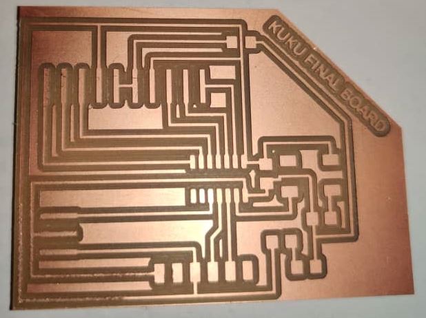
Designing my PCB Board
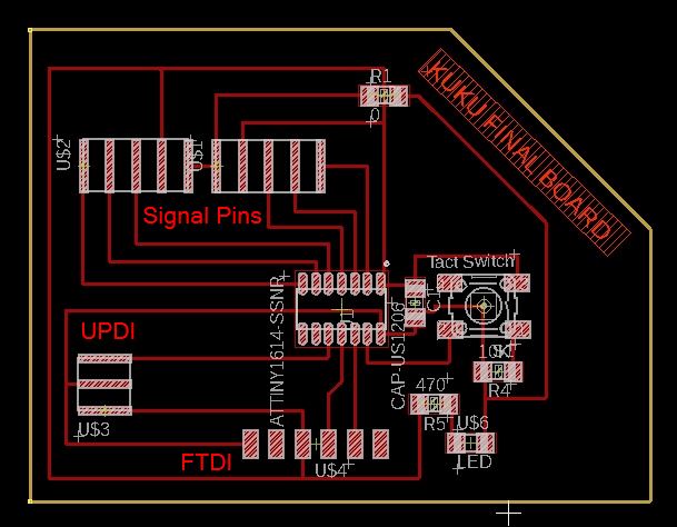
I designed my board using Eagle software. I used the existing design of my Output board and added additional signal pins since I'll be using 3 PIR sensors, 1 LDR sensor, a speaker and LED strip.
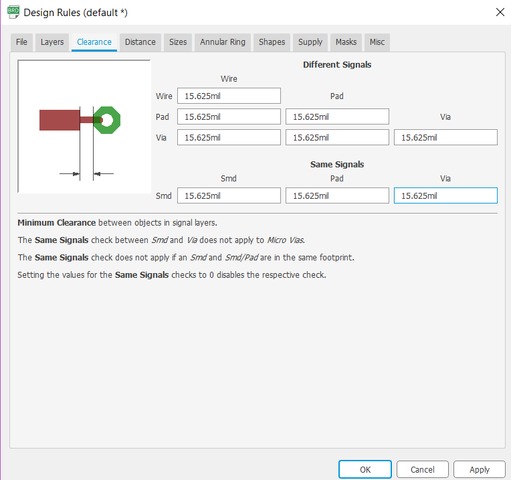
As suggested by our Local Instructor Mr.Rico, I changed the design rule according to the machine and the endmill I was using.
Used 10 as the width size of the traces.
This is how my board turned out
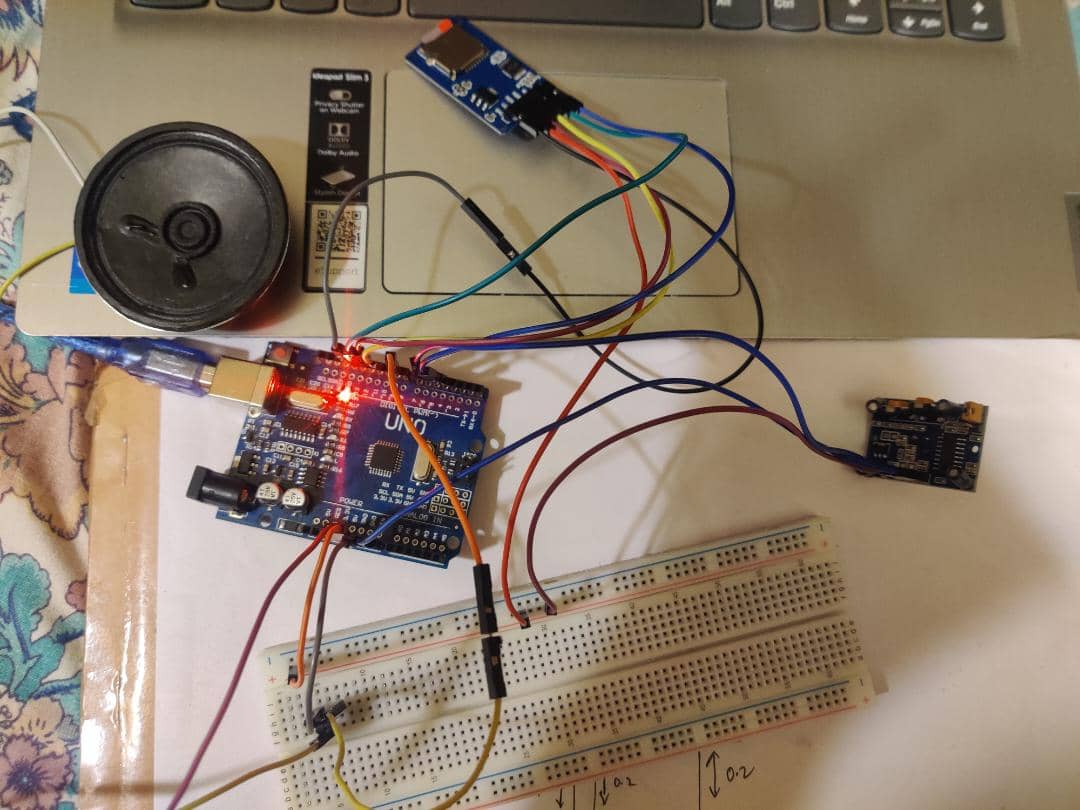
Testing PIR with the Speaker using Arduino
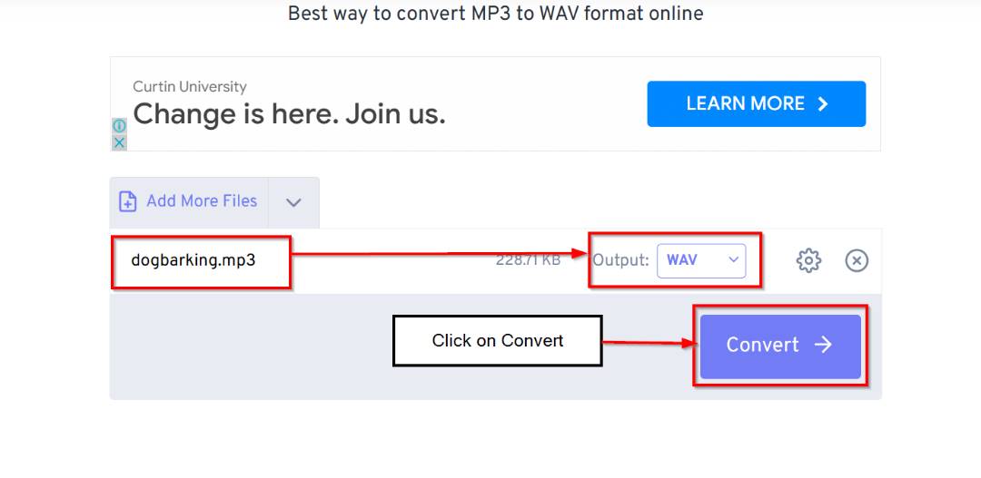
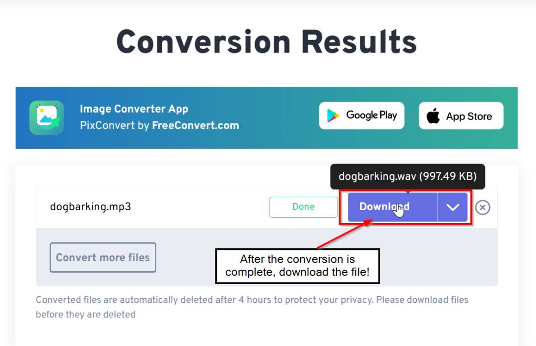
First I downloaded a Dog barking sound from Youtube in mp3 format. Then I had to change the audio file from mp3 to wav format so that the SD Card Module can read.To do so I used an online convertor
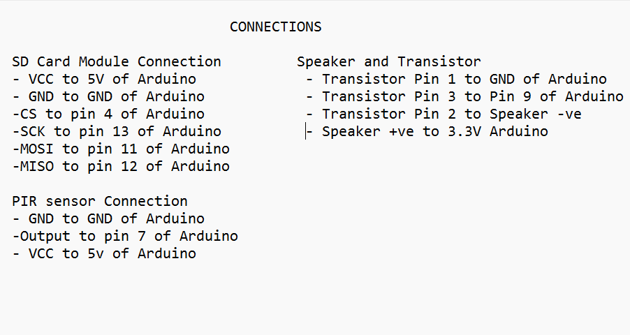
Then after getting the audio in wav format, my next step was to do the connections of the components.
After the connections were completed, I transferred the wav audio file to the SD card.
Now programming, I got the code from here and I made some changes according to my connections.
After the code got uploaded and compiled, I couldn't hear the audio. Just some buzzing sound which was a disappointment.
Using DFplayer in place of Mp3 module
Mr.Rico upon arrival to Bhutan to guide us to complete our Final project on time, he brought with him the Dfplayer which was much more user friendly and I didnt even need to change the sound format to wav form.
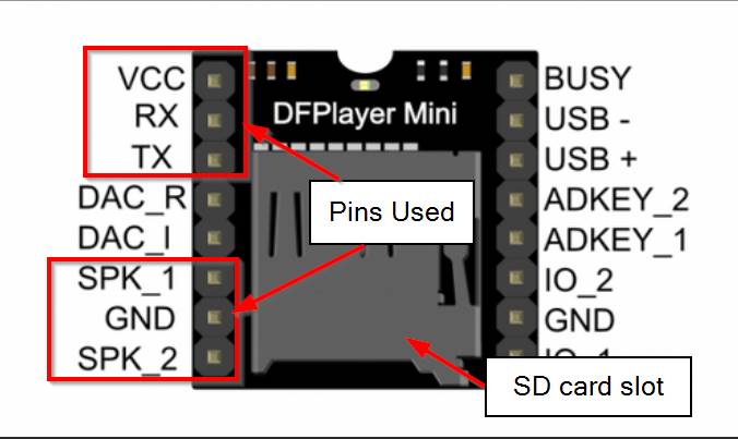
This is the pinout for the df player mini.
I referred this Youtube Video which was similar to what I was trying to achieve.
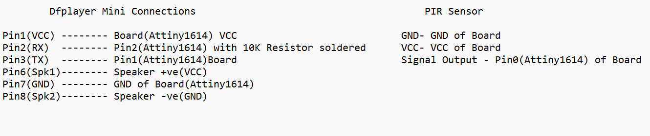
Connections made between DFplayer, Speaker and the board with the PIR sensor.
After the connections were made, I got the code from the same youtube video and had to change the pins according to my connections.
  #include "SoftwareSerial.h"
  #include "DFRobotDFPlayerMini.h"

  SoftwareSerial mySoftwareSerial(2, 1); // RX, TX
  DFRobotDFPlayerMini myDFPlayer;
  void printDetail(uint8_t type, int value);

  #define SENSORPIN 0
  #define PAUSETIME 1000

  void setup() {
    mySoftwareSerial.begin(9600);
    Serial.begin(115200);
    pinMode(SENSORPIN, INPUT);

    Serial.println();
    Serial.println(F("Initializing DFPlayer..."));

    //Use softwareSerial to communicate with MP3
    if (!myDFPlayer.begin(mySoftwareSerial)) {
      Serial.println(F("Unable to begin:"));
      Serial.println(F("1.Please recheck the connection!"));
      Serial.println(F("2.Please insert the SD card!"));
      while(true);
    }
    Serial.println(F("DFPlayer Mini online."));

    //Set volume value (From 0 to 30)
    myDFPlayer.volume(30);
  }

  void sensorActivated() {
    int pirSensor = digitalRead(SENSORPIN);
    if(pirSensor == HIGH)
    {
      Serial.println("Sensor Activated");
      Serial.println("DFPlayer Working...");
      myDFPlayer.play(1);
    }
    return;
  }

  void loop() {
    sensorActivated();
    delay(PAUSETIME);
  }
This is a working video of the speaker with PIR sensor and different output sounds.
Final Code and Final Connections of All output(Speaker and LED) and all Input(PIR and LDR)
This is the final code used. I compiled the LDR and PIR with LED and Speaker code.
  ba#include "SoftwareSerial.h"
 #include "DFRobotDFPlayerMini.h"

 SoftwareSerial mySoftwareSerial(2, 1); //RX, Tx
 DFRobotDFPlayerMini myDFPlayer;
 void printDetail(uint8_t type, int value);

 int LDRInput=3; //Set Analog Input 3 for LDR.
 int LED=4;
 #define SENSORPIN 0
 #define PAUSETIME 1000

 void setup() {
   mySoftwareSerial.begin(9600);
   Serial.begin(115200);

   pinMode(LDRInput,INPUT);
   pinMode(SENSORPIN, INPUT);
   pinMode(LED,OUTPUT);

   Serial.println();
   Serial.println(F("Initializing DFPlayer..."));

   if (!myDFPlayer.begin(mySoftwareSerial)) {
     Serial.println(F("Unable to Begin:"));
     Serial.println(F("1.Please recheck the connection!"));
     Serial.println(F("2.Please insert the SD card!"));
     while(true);
   }
   Serial.println(F("DFPlayer Mini online."));

   myDFPlayer.volume(30);
 }

 void sensorActivated() {
   int pirSensor = digitalRead(SENSORPIN);
   if(pirSensor == HIGH)
   {
     Serial.println("Sensor Activated");
     Serial.println("DFPlayer Working.....");
     myDFPlayer.play(1);
     for (int i = 0; i<=3; i++){
     digitalWrite(LED,HIGH);//The LED turns ON in Dark.
     delay(300);
     digitalWrite(LED,LOW);//The LED turns OFF in Light.
     delay(300);
     }
   }
   return;
 }

  void loop() {

   int value=analogRead(LDRInput);//Reads the Value of LDR(light).
 Serial.println("LDR value is :");//Prints the value of LDR to Serial Monitor.
 Serial.println(value);
 if(value<850)
   {
     digitalWrite(LED,HIGH);//The LED turns ON in Dark.
   }
   else
   {
     digitalWrite(LED,LOW);//The LED turns OFF in Light.
   }

   sensorActivated();
   delay(PAUSETIME);
  }